
Ed, I see that you may be right; Color Gotcha might just have been one of the first if not the first color video game. – Al Alcorn 4/28/2016
TLDR – Printed circuit board from the long lost first color arcade video game found, repaired and first pictures and video posted online.
A few months ago I was walking around the largest gathering of game developers in the world (a conference called GDC) asking everyone I know a few simple questions: “What was the first arcade video game?” (some knew it was “Computer Space”) If they got that right I’d ask: “What was the first game from Atari?” (easy, “Pong”) and if they got that I’d ask them the killer final question: “What was the first COLOR arcade game?” Nobody knew the answer. Then I would tell them a crazy story of a long lost machine, with the punchline being that the printed circuit board for one of these machines was for sale, that week, on eBay, and I intended to buy it and bring it back to life. That is the story I will tell you now.
But first a little background…
Near as I can tell, the early history of arcade video games goes like this: In 1971, Nolan Bushnell and Ted Dabney create the first arcade video game with the release of “Computer Space” through Nutting Associates (see Fixing Computer Space). In 1972 they start Atari and hire a young engineer, Al Alcorn. They assign Al a warm up project to make a simple tennis game using the same basic circuits and ideas that Nolan and Ted had developed for Computer Space. Surprisingly this simple game, “Pong”, becomes a huge success and quickly spawns a multitude of imitators. Meanwhile Atari continued to innovate, releasing “Space Race”, the first racing game in July of 1973 and “Gotcha”, the first maze game in October of 1973. (The hardcore history buffs will correct me if I don’t mention that Atari also released a 4 player version of Pong at this same time called “Pong Doubles”).
This is where things get interesting…
Gotcha is a two player game where one player chases the other through a constantly changing maze. The maze is based on a bug from when Al Alcorn was making Pong. He accidentally caused the score to be repeated over the whole screen. This gave him the idea to use the score character generator to build a maze. To make the game more interesting during the free love era of the early 70s, Nolan’s design director George Faraco had a radical idea. He proposed that they should cover the two joysticks with pink silicone domes. Let’s be clear, they looked like breasts.

By pushing these breasts the two players could chase each other around the maze. As you might imagine, this is often reported as the first controversial video game in history, and eventually Atari was forced to revert to simple joysticks for the game. You can read more about that here.
But it turns out Gotcha may have been first in another category too. Supposedly, a small number of color versions were produced, and if they were released at the same time as the black and white version, in October of 1973, then they would likely be the first color arcade games in history. As far as I know, no one has seen one of these machines for decades. If you search “Color Gotcha” Atari you will find only a handful of pages of links, almost all of which are irrelevant. You will find no images or video.
We’re talking about the first color arcade game in history! How can there be no images online? I set out to change that.
Over the last year I had been reading what history I could find and looking for new projects to work on in my spare time. I had so much fun Fixing Computer Space that I needed a new challenge. I spent a few months fixing a Space Wars from 1977 (something I still need to write up) and then I decided to see if I could go back to the beginning of arcade video game history and work my way forward. Since I had already done Computer Space, the next obvious choice was Pong. I searched for a few months for a full Pong arcade game without much luck, but I did see some printed circuit boards (PCBs) come up for sale. Maybe I should just get the PCB and hook that up? So I did.
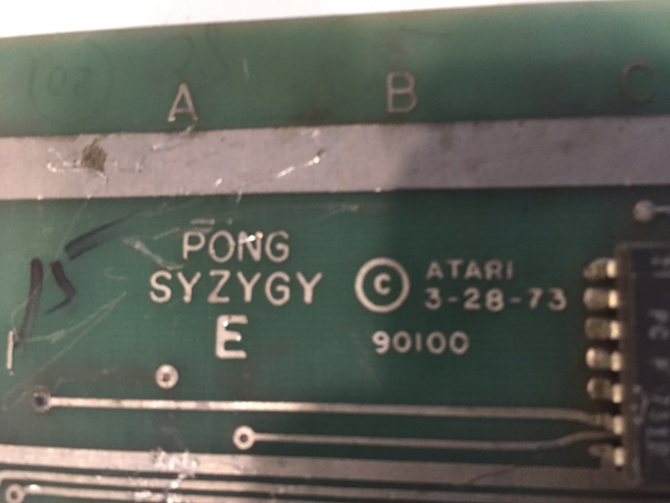
For less than a hundred bucks I was able to get a Syzygy branded Pong board and build a custom connector to bring power and controls in and sound and video out of the board. Once the connector was complete, the damn thing just worked. Over 40 years old and nothing for me to fix. What fun is that?
So I moved on to the next board on my list: Space Race. I kept an eye on eBay and about a month later someone listed a Space Race board (actually he listed a bunch of them). I was so excited I snapped one up without doing my homework. When it arrived I realized I had been had. I was holding some kind of knock-off pong clone, not the Space Race I so dearly desired.

How could I tell it was fake? Well by then I knew that one of the cool things about Space Race is that integrated circuit read only memories (or ROMs for short) were too expensive to use on something like this in 1973, so if they wanted a bitmap for graphics they had to lay it out as a set of diodes on the board. On Space Race they made half the spaceship this way and then mirrored it in hardware.
I waited and eventually a real Space Race PCB showed up on eBay, with a sub $100 price and a buy-it-now button. I bought it. In fact a whole bunch of pre-1975 Atari boards came up for sale all at once. I bought one of each type. The seller combined my boards into one big box and promptly shipped it to me. I finally had my Space Race and started to work to bring it back to life.
Instead of hardwiring controls to the connector like I did with Pong I thought it might be smarter to build a connector that mapped the outputs to some kind of standard (learned this trick by reading stuff by the amazing arcade restorer Andrew Welburn at http://andysarcade.net). I purchased a standard JAMMA harness with buttons and two joysticks off eBay and a simple wood enclosure to mount them in and then built the connector for Space Race.
Fortunately the Space Race board had several problems and provided me with hours of repair entertainment. In fact I still have to fix the sound for player two, but I got it mostly running before getting distracted by a more important project… Here’s an early video I shot while it still had a few problems:
So I was working on Space Race and keeping an eye on eBay and the same guy that I bought all those boards from posted a bunch of new boards. I had been reading pretty much everything I could find online about the early history of Atari and that included many articles from “The Golden Age Arcade Historian” whose incredible detective work I had discovered while fixing Space Wars. In particular I had just read this short article which I strongly recommend you read now: Read Me.
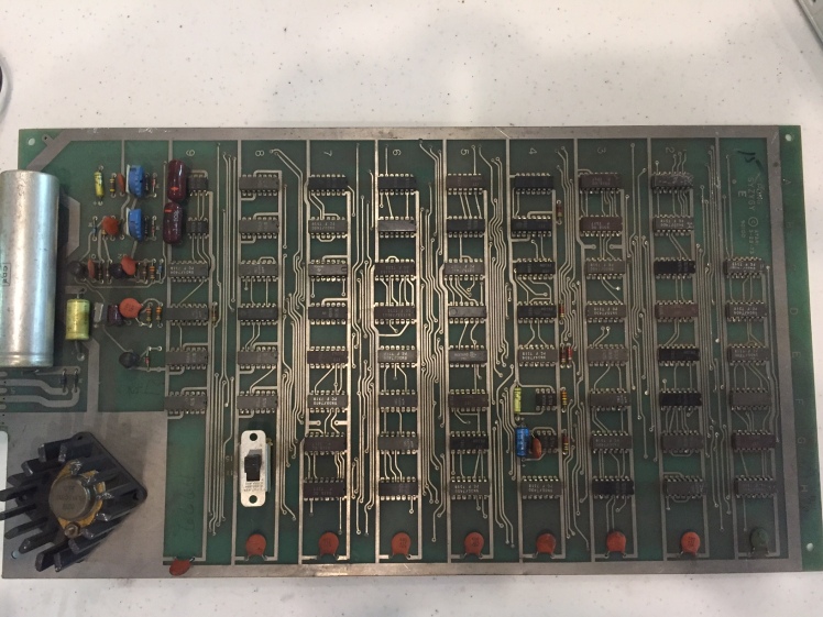
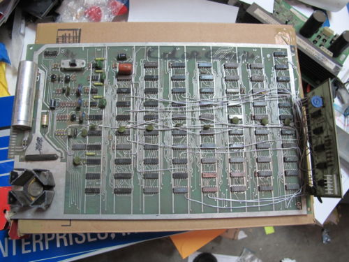
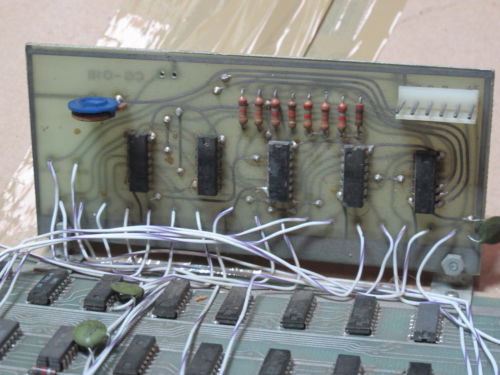
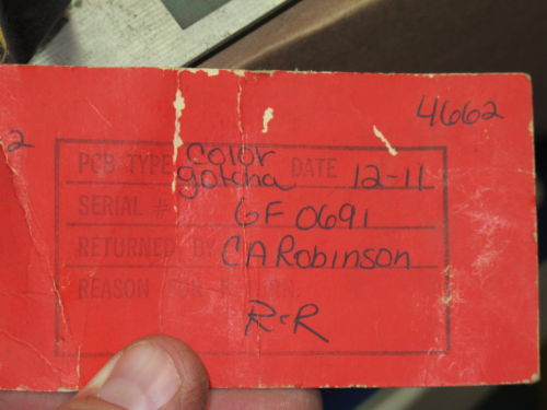
As I looked through the new boards on eBay I was dumbfounded to see one titled: “Atari GOTCHA COLOR pcb from 1973 w/ Atari Service tag attached!” and that’s what it was. Here are the images the seller posted:
There was no buy-it-now price so I’d have to fight it out with other bidders. Maybe no one else would notice, know, or care what it was? As it turns out, despite my running around GDC foolishly promoting the existence of the board, only one other person bid on the board. But two is all it takes to drive up a price in an auction and my final purchase price was $760.
Kind of a crazy price for just a printed circuit board, but this was an important piece of history, or at least that’s what I told my wife…
The board arrived along with several others and I was so excited I immediately posted something on Facebook so that my friends from GDC would know I had succeeded in the first part of my quest:

What is the worst thing that could happen after a post like that? How about this:

That’s right, almost immediately, THE Nolan Bushnell replied to my post saying the new purchase I was so proud of was garbage. My heart sank.
But wait a minute… There were a couple things that were clearly wrong with what he said. Even if Color Gotcha didn’t exist (in which case, what was I holding?) I knew for sure that they had released the color game Indy 800 in 1975. I was literally running out the door to pickup my oldest son and some friends from a birthday party when Nolan’s post popped up. I tried to write something quick that said “No, you are wrong about what your own company did over 40 years ago.” But in the nicest way possible. I wrote:

Fortunately his next post struck a more conciliatory tone:

With the first disaster averted I started to make plans to bring the board back to life. I had also purchased a regular black and white Gotcha board from the same seller. The Color Gotcha looked to be in better shape but I decided to warm up on the B&W Gotcha before I tackled the really important one.
Then, unexpectedly, the seller contacted me over email and offered to sell me a second Color Gotcha board which he said was in much worse shape. He included pictures including this one where you can see the color daughter board has been cut badly in several places. I thanked him but passed. I wasn’t trying to corner the market on these things and I hope he sold it to the other guy I outbid in the first auction.
I also asked the seller, Stephen Beall, where he found these boards. He said:
“I have an op [arcade route operator] friend I’ve known for years. I’ve gotten all kinds of goodies from him since the 80’s. He’s been in business since the mid 70’s and instead of buying the latest and greatest from C.A. Robinson (biggest game distributor in Los Angeles, closed in 2010) he would always ask to go in the “back warehouse” and get the stuff that was a few months or few years older. He’d save money that way since our area didn’t need the latest equipment to make money. The color Gotcha’s were something he probably got back in 1975 for $95 each.”
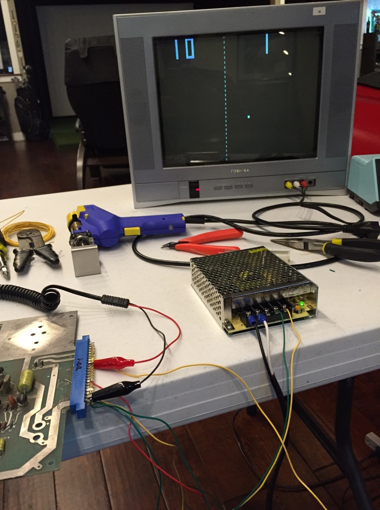
The B&W Gotcha looked a bit beat up. The most obvious problem was a stray wire hanging off the board. Where was the wire supposed to connect? I had no idea. I found a schematic on the net but it was for the F version of the PCB and I had the earlier C version. None of this filled me with confidence, but I built a connector anyway and hooked up power in and video out to see what I would get. What I got looked like this:
Okay so the two players are showing up but the maze is completely missing. Using my logic probe and the schematic I tracked backwards from where the maze was generated until I got to a chip that should have been outputting it but wasn’t. One pin didn’t seem to be getting a signal but I didn’t know why. Normally I can see a trace on one side of the board or the other, running to a pin so I know where the signal is coming from, but I didn’t see one on either side. Sometimes though, the trace is underneath the chip so you can’t see it. I assumed that’s what was happening and quit for the night.
The next day I started fresh and considered my two problems: I had a wire hanging out that should be attached somewhere and I had a pin that should be getting a signal but wasn’t… You don’t suppose… I touched the wire to the pin and the full and correct image of Gotcha appeared! It looked like this:
Wow, that was easy! I guess I can start working on the Color version! And so I did.
Unfortunately I wasn’t so lucky this time. Because Color Gotcha is a modified version of B&W Gotcha I hoped that I could get the B&W part of it working first and then worry about the color. It turns out this isn’t really possible but it took me days to understand why. What happened when I first plugged it in was… nothing. There was a vague shimmer on the screen but nothing recognizable. No maze, no players, no nothing really. But when I hooked up the logic probe and started poking around it seemed to be happily humming away doing something.
I poked and prodded until I found something that was clearly wrong. Pretty soon I located a chip that obviously wasn’t doing its job. Signals were coming in but not coming out, or at least not coming out the way they should. I pulled the bad chip and put in a new one and something showed up on the screen! It was one of the players (just a small square really) and it was trying to move around but the whole image was rolling. Clearly the sync signals that stabilize the TV image were screwed up. I had just had this problem on Space Race so I knew where to look and what to look for but everything seemed fine on my oscilloscope.
Since I didn’t understand what was going on with the sync signal, I explored more and discovered another problem. A counter chip responsible for the horizontal positioning of player two was clearly not counting.
I’m going to insert a kind of long, “super technical” section here about how and why these early TTL games use lots of counter chips. I’m doing it because I think it’s really interesting, but there might not be more than three other people on the planet who feel the same, so if this doesn’t sound really interesting to you, feel free to skip to the end of the “super technical” section. I promise you won’t miss anything important to the story.
When I was fixing Computer Space, I didn’t really understand how these machines worked. I looked for chips that weren’t acting the way they should and replaced them when necessary, but how do those chips add up to a whole functioning game? What I now understand is that the games are fundamentally built out of a series of counters (sometimes called “slipping counters”) and the way these counters work to keep track of the horizontal and vertical position of animated objects is really different than we tend to think about doing it in software.
All of this is explained in MUCH more detail here: “The Textbook of Video Game Logic, Volume 1”.
Okay, so the first thing to understand is the game starts with a clock, tick tocking away. The clock on these boards is ticking very fast and the rate is chosen carefully to line up with the rate of a US television signal. The clock pulse is fed into a counter chip (actually a couple of 4 bit counter chips and flip-flops for extra bits but let’s ignore that for now). This is the horizontal sync counter and its job (on these early boards) is to count up to 452 and then start over again at zero and do it again. If a different clock rate were chosen it could run faster or slower but its rate effectively determines the horizontal resolution of the graphics. In fact the output from the horizontal counter is used all through the game to determine the X position of objects on the screen.
Every time the horizontal counter resets it sends a tick to the vertical counter. Again it’s a simple counter (we’ll pretend it’s one chip but it isn’t…) that counts from 0 to 262. Unlike the horizontal counter you can’t mess with the number of vertical positions because it’s defined by the television standard (unless you implement interlacing, which doubles the vertical resolution) so you are stuck with 262 lines. The output of the vertical counter defines the Y position on the screen.
Not all the horizontal positions are actually visible on the screen, nor are all the vertical positions as some are allocated to sending special synchronization signals to the TV to define things like horizontal and vertical sync and blank. I only put this here so someone doesn’t accuse me of lying to you. Feel free to forget it now.
Okay so we have an X and a Y position. As a programmer I would think that if someone wanted to put something at a certain place on the screen they would wait until X and Y match that position and then they would spit it out. And that’s exactly how non-moving elements of the screen tend to be done. The score would be a good example of this. But what about moving objects? This is where things get weird in the land of hardware…
If I wanted to put a moving object on the screen, say, the ball from pong, the way I would do it in software is I would have an X and Y variable that I could change over time. Then I would compare the screen X and Y to my variables X and Y and when they matched I would output the ball. But surprisingly that’s not how it works. Mind you it COULD work that way but that’s just not the way they did it. I’m not entirely sure why. At first I thought it was just dumb… but I actually think it uses less chips if you do it this way and I’ll try to explain why. But first let me explain what they do.
Instead of using a variable that stores (say) the X position. They have acounter that is humming along incrementing every time the master horizontal counter increments (say what?). The thing is, this counter is out of sync with the master counter, so at some point it reaches its maximum count and resets to zero and AT THAT POINT it outputs the image of the ball (assuming we are on the line where the Y position vertical counter also reset).
So the degree to which these horizontal and vertical counters are out of sync from the main counters determines where the ball is on the screen. Okay, once you’ve wrapped your head around that you might want to say, “sure Ed, I get that, but then the ball would be sitting still. I thought you were going to make it move?” and to that I say, “I am, just watch!”
So the counters are doing their thing, counting up and resetting to zero over and over, but what if we don’t reset them to zero? What if we nudge their count forward or back a bit or two? Then the next time around the counter will reset when the master counter is at a different place on the screen! By nudging (or “slipping”) these counters forward or back we can move the object around.
Okay, I’m almost done. I just want to take a minute to describe why (I think) they do things this somewhat wacky way (other than that they are electrical engineers and not programmers so they see the world differently…). The cool thing about this system is there doesn’t need to be any circuitry to compare the X variable to X master location (and same for Y), we just have to know when the counter resets. Also we don’t need to have circuitry to add or subtract something from the X (and Y) values, we just nudge the counter one way or another when resetting it to move the object.
The downside, I guess, is we don’t really have the X and Y position of any moving objects stored anywhere. If we really needed them that would be a problem, but these games tend to deal with (for example) collision detection in different ways so apparently knowing the X and Y of something isn’t usually an issue.
I didn’t have the counter chip I needed so I got to make a trip to my favorite electronics store, Vetco. I replaced the chip and now I had both player 1 and player 2 bouncing around on my still rolling out of sync screen. I guess I was making progress…
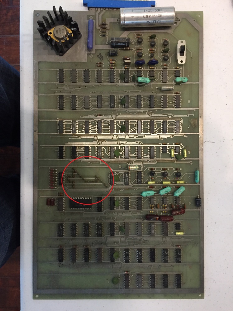
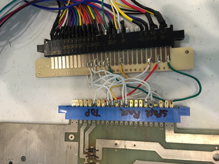
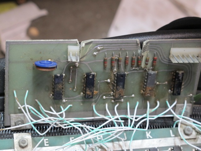
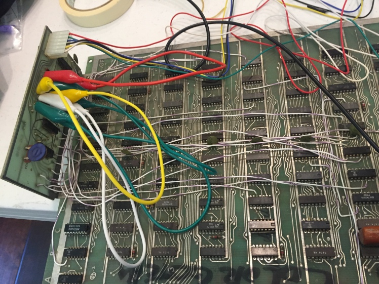
At this point I spent a while poking around looking for something else that was broken. I kept coming back to the sync signal being wrong (which is why the screen was rolling) and eventually I noticed that several traces on the board had been deliberately cut:


My theory up until now was that the B&W part of the Color Gotcha should still work and that they were just siphoning off signals here and there into the color daughter board to send out to the color display, but now I had examples where that was clearly not true. To make progress from here I would have to tackle the color signal. Well… maybe it’ll just work? I had the connector I needed to hook up to the output of the daughter board so I plugged that in and soldered the appropriate wires to the right pins on my JAMMA connector. Now I just happen to have an old Scramble arcade cabinet that I converted to JAMMA so in theory I should just be able to plug this in and it will work…
So I plugged it in and… it didn’t work, at all. All I saw were sparkly dots on the screen. It looked really bad, honestly. Oh well, back to the drawing board.
I looked at the sync signal line with my oscilloscope and it looked like a sync signal, as far as I could tell. So I looked at the color signals and saw that there was almost no signal at all coming out. Maybe that was the problem? The last chip the three color lines (Red Green and Blue) went through before going out the connector to the monitor was a 7405 “open-collector” inverter. Since I didn’t know what “open-collector” means I ignored that and concentrated on the inverter part. I could clearly see what looked like good signals coming in to the inverter but (almost) nothing coming out. In the past this has always meant that the chip was bad so I drove to the store, got a replacement, removed the old chip, soldered in a socket, plugged the new chip into the socket and… it behaved exactly like it did before. It still had no signals on the color pins and when I plugged it into the JAMMA machine it still made sparkly dots which looked like the sync was bad. It looked like this:
This was probably the low point of this project. I really didn’t know what was going on and I wasn’t sure how to make progress. The B&W output was screwed up for reasons I was pretty sure I understood (cut traces). The color output was screwed up in ways I really didn’t understand. To make progress I needed to learn more about how arcade monitors work.
After a good night’s sleep I came in with a crazy new plan.
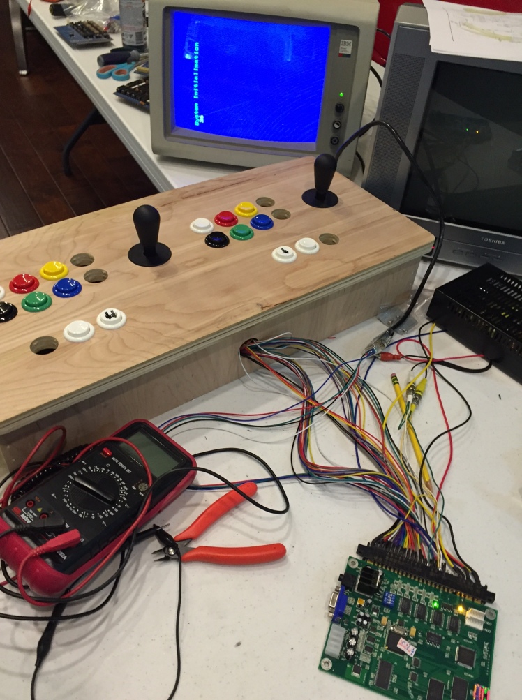
It was hard to debug anything when it was plugged into the Scramble cabinet and I didn’t have a CGA arcade monitor just lying around that I could throw on my workbench, or did I? I had an old IBM 5153 CGA monitor hooked up to my IBM PC/XT. Maybe I could use that? Some browsing on the internet gave mixed signals. I decided to go for it anyway. Another trip to Vetco got me the 9 pin connector I needed and I soldered it up to the JAMMA harness.
With that in place, I should, in theory, be able to plug any JAMMA board into my harness and see it on the screen. Better test it with something I know works first, so I plugged in the only JAMMA card I own, a 60 in 1 game card. And it worked!
Sort of…
The colors were clearly messed up but I decided this was because the IBM CGA monitor was only designed to display a few colors. Now I could plug the Color Gotcha board in and… it still didn’t work. But it didn’t work less badly! By that I mean that the output wasn’t sparkly. There was a solid picture. It was just a solid picture of nothing. So why did it work? In all this messing around I had learned that there are two kinds of sync signals: Positive Sync and Negative Sync. This monitor can handle a positive sync. My other monitor was (when I went back and checked) wired for negative sync.
Not only did I have a solid sync, but I could jumper signals around that final 7405 chip and see things appear on the monitor that sort of looked like Color Gotcha.
At this point I knew I was going to make it.
I just had two problems left to solve. I needed to understand how the 7405 was supposed to work and I needed an appropriate monitor to hook the game to. The answer to the second problem was staring me in the face: Robotron. The only other CGA monitor in my “office” is a Robotron. It’s horizontal, which is perfect for Gotcha. The only reason I hadn’t used it earlier is because it’s not wired up to be JAMMA. But what if I made a custom connector from my 9-pin connector directly into the CGA monitor? That should be perfect. The monitor even has separate inputs for positive and negative sync. All I need is… another trip to Vetco for parts.
But before I did that I also needed to solve the 7405 problem. The 7405 is the “open collector” version of the “7404”, whatever that means. I looked over the datasheet for the 7405 and saw phrases like “pull-up resistor” and “wired ANDs”. Maybe I needed pull-up resistors on the output side of the 7405? I knew a pull-up resistor was a resistor that sits between +5 volts and a signal line but beyond that I wasn’t sure. Time to call my electrical engineer brother. Fortunately, during our conversation, he mentioned the potential need for pull-up resistors, completely unprompted by me. That seemed to be the solution. He also mentioned that he thought the video signals might be inverted. Why he thought that, I’m still not sure.
The next day I prototyped a little circuit. I wasn’t sure what value pull-up resistor to use so I used a variable resistor with a range of zero to 50K ohms which seemed like more than enough. I hooked it up to the output side of the red signal and as soon as I turned it on I could see a happy signal coming out of the 7405 as I had hoped. Even better the single pull-up resistor seemed to cause all three signals (red green and blue) to come to life. I quickly finished connecting it to the monitor and saw the first image of Color Gotcha. It looked like this:

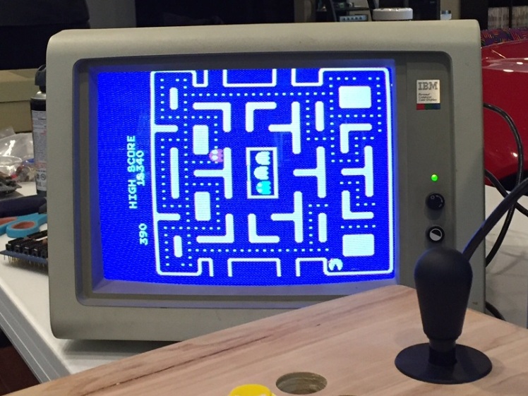
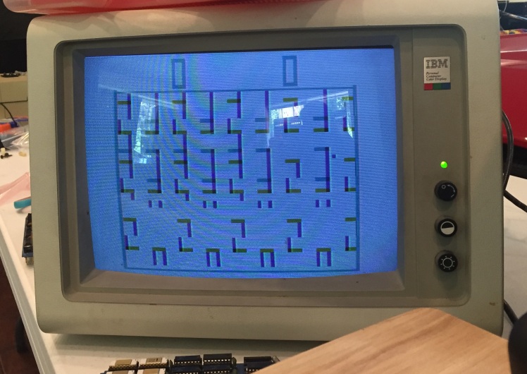
Sure enough, the colors looked inverted, just as my brother predicted. I scrounged up a 7404 (chip with a bunch of NOT gates) and ran the signals through that to invert them one more time before sending them out to the monitor. This time I got what I believe is the true Color Gotcha image. It looks like this:

Hallelujah!
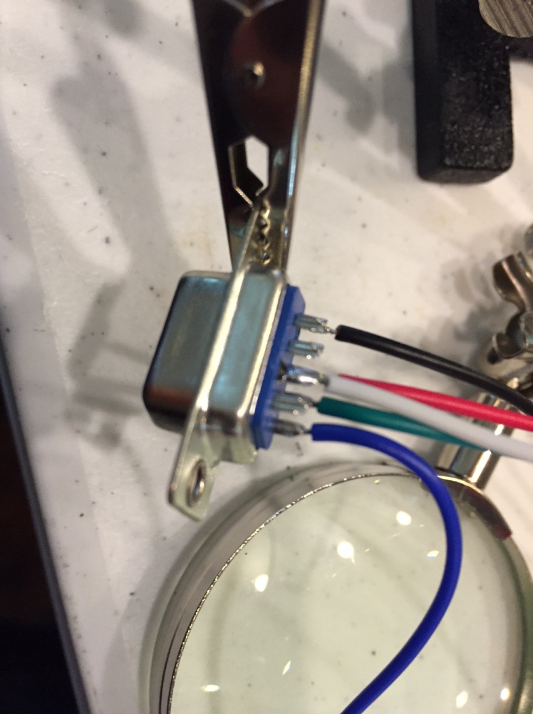
I can’t tell you how exciting this moment was. Could I be the first person to see the first color arcade game in decades? Maybe so! At a minimum I was going to be the first person to post pictures of it on the internet. I still had a lot of cleanup work to do though. First a trip to Vetco got me a little board that I could use to solder up my prototype pull up resistor/inverter board. The finished thing looks like this:
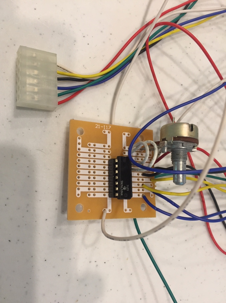
I also had to finish the wiring harness to make the game actually playable. That involved adding more wires to my JAMMA adapter. The final version looks like this:

Here’s a video of the finished game in action:
I was done and it works!
So all that leaves is the big question: is Color Gotcha the first color arcade game? Keith Smith, the writer of the Golden Age Arcade Blog says it “probably is, but it’s a close thing”. His most recent information on the topic shows the other contender, “Wimbledon” by Nutting Associates, shipping within a month of Color Gotcha: http://allincolorforaquarter.blogspot.com/2013/12/chasing-down-rabbit-trails-fun-and-food.html
I wanted more proof.
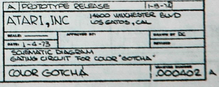
It was clear from Nolan’s comments on Facebook that he wasn’t going to be the source of reliable information on the topic. But he did mention the original designer of Gotcha, Al Alcorn. Maybe Al would remember something? I tried sending a LinkedIn request to him and didn’t get a response, but I did notice my friend Jeri Ellsworth was connected to him. At my request she sent a nice introduction mail to which he responded right away. He was very willing to help. Unfortunately after a few exchanges it was clear that he didn’t remember the color version at all. I sent him the schematic and a picture of the color version of the game running but he still wasn’t sure. I pointed out the schematic (from an old Atari manual called “Computer Games Operators Handbook”) has two dates. On the left it says 1-4-73, which is too early to be believed and is probably a mistake. On the top right it says 1-8-74 which is after the release of Wimbledon but this schematic could easily have been drawn up after the game was completed.
The schematic offers one more intriguing clue. It says “drawn by DC”. I asked Al if he might know who DC was and he said it might be “Dan Corona”, a tech he hired and trained around that time. I have reached out to Dan via Linkedin and Facebook but so far no luck.
At this point I sent mail to another friend, Van Burnham, who co-owns Supercade, which, as far as I know, is the largest collection of classic arcade games in the world. Her response came as quite a shock. It turns out she also has a Color Gotcha board but has never tried to get it working. So that means at least three still exist. I offered to bring my harness and try to get hers running next time I’m in LA.
Finally I reached out to Marty Goldberg who, along with his partner Curt Vendel, literally wrote the book on the early history of Atari: ataribook.com. Marty was adamant that Color Gotcha is the first color arcade video game and he gave several forms of proof. He pointed me to an internal Atari document, released a few years ago, that lists the release date, price, and in some cases quantity produced, of all games made by Atari between 1972 and 1999. It shows Gotcha and Color Gotcha releasing simultaneously in October 1973. See that document here.
Marty also referenced two lines from the very detailed (and supposedly very accurate) timeline of Atari by Michael Current (http://mcurrent.name/atarihistory/syzygy.html).
The first says “October (73): Atari released both Gotcha and Gotcha Color, a limited-run color version of the game that used real color.” This matches the Atari internal document above.
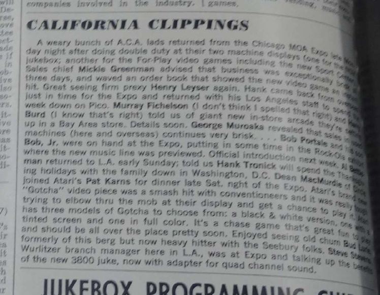
The second says “November 9-11: Atari featured Pong, Space Race, Pong Doubles, and introduced Gotcha at the 25th anniversary Expo ’73, the Music and Amusement Machines Exposition sponsored by the MOA at the Conrad Hilton Hotel, Chicago. Atari showed three versions of Gotcha: black & white, tinted screen, or full color. (Cash Box 11/24/73)”
(Update 5/27/2016) Keith Smith was able to track down a scan of the article from the 11/24/73 issue of Cash Box:
Because Marketplace Magazine tracked the price of Color Gotcha and also because it was included in Karz-Kursch service training events in 1974, Marty’s educated guess is that Color Gotcha was not a mere prototype, but that at least 20 and perhaps as many as 100 were produced.
Keith Smith, the writer of the article that started all this, sent me mail in which he gave me the evidence on both sides and concluded with “From the evidence I have (which is far from conclusive), it looks like Color Gotcha came about in October and Wimbledon in late November.”
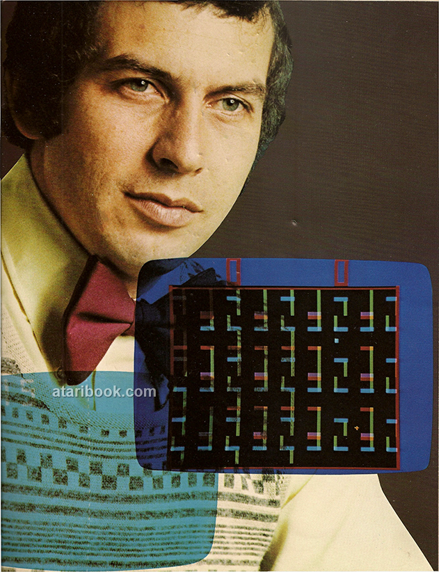
As one last act of kindness, Marty sent me the image below, along with permission to include it here. The image comes from the first brochure Atari ever produced and may be the only one in existence. It belongs to Marty and Curt as part of their Atari Museum collection in New York. It has never been published before. As you can see it shows a youthful Nolan Bushnell, looking dapper and visionary, with an image of Color Gotcha superimposed below his chin. It’s an image that looks a lot like the one that I made:
So that’s the story.
If you read all the way to here, I am impressed! Thank you for taking an interest in my work. Thanks also to Stephen Beall, Marty Goldberg, Keith Smith, Van Burnham, Andrew Welburn, Al Alcorn, Nolan Bushnell, Jeri Ellsworth, my brother Bob, and everyone else who helped and encouraged me along the way.

I have a cocktail goal IV machine qand no almost nothing about it..July of 1975…and there were 595 of them created.
Sid seattle
LikeLike
A cracking read that. Really enjoyed the tale. Props to you sir!
LikeLiked by 1 person
Thanks for the kind comment. I’ve really been enjoying your stuff as well.
LikeLike
Awesome work. I’ve long wondered about both Color Gotcha and Wimbledon as I came across the same dilmema when doing research on early 70s arcade titles. I’ve never seen a Wimbledon apart from the flyer…did come across a video that purported to be Color Gotcha a long time ago but it only had the player objects with any color. Good thing you didn’t give up on getting that working, it is great to see what this actually looked like in operation. Makes me surprised that they didn’t tout it more.
LikeLiked by 1 person
Loved the read! And the “super technical” part wasn’t all that technical (and quite entertaining!).
LikeLiked by 1 person
Well done!
Your section on the counters, and X and Y locations reminded me that on the Atari 2600 you don’t need to keep track of X locations for objects. If you check the disassembly for Combat you’ll see RAM allocated for TankY0, TankY1, MissileY0 and MissileY1 but nothing for X positions:
http://www.qotile.net/minidig/disassembly/dicombat.asm
Instead, at the start of each match Combat uses the RESPx registers to set the players (sprites for those unfamiliar with 2600 terminology) to the left and right sides of the screen, then over successive frames it uses registers HMPx to move then left/right over successive frames. For the missiles (the single pixel sprites) it uses RESPMx to center them within the players, then uses HMMx to move them.
LikeLiked by 1 person
Hi Darrell,
This is exactly right. What feels like an awkward way to position sprites on the 2600 is exactly like the slipping counters used in all these early games. Even the HMxx register is the same as the “nudging” the counter I mention in the writeup (except they tend to only use 3 bits instead of the 4 used in the 2600. The 2600 designers must have been influenced by these early games when designing their sprite system.
LikeLike
Nice read. I liked the super technical part. I hope to be able to tinker like you are doing some day too.
LikeLiked by 1 person
Well done!! Keep up the good work!
LikeLiked by 1 person
Impressive research work, absolutely amazing. I’ve really enjoyed your tale. I’ve always think that “Wimbledon” was the first color video game, but your findings will set another first for Atari. I must say that outside USA (and also inside USA if we consider that was a very limited production) the “color gotcha” was probably never seen… In Italy (and in Europe generally) we remember only Wimbledon arrived in 1974 (this link is a scan of an adv taken from an italian magazine pubblished in june 1974) http://www.retroedicola.it/_archivioSpeciali/Automat/061974//originali/025.jpg
LikeLiked by 1 person
Thanks Carlo, that’s very interesting. Given what I’ve seen it seems likely that Color Gotcha beat Wimbledon to market by at least one month but you are right to wonder to what degree it was produced. Marty mentions that people were trained to service it and that it shows up on the official Atari sales list so that seems to make it more than just a prototype but how many were produced? We may never know.
LikeLiked by 1 person
Hi I worked at Sysygy – Atari and worked on Pongs, Space Race, Gotcha, Astroids, Star Wars, Race Driven
I kind of remember that board with all the Mods
I was a production tech and then went to customer / field service
A trick I used to use when troubleshooting was to just bend in the pins of of an IC and put it on top of a suspected bad IC – this would work if the original outputs were floating and for timeing problems with certain IC’s
It would not work IC the original output was grounded
Thanks for the flashback
Mark sherman
LikeLiked by 1 person
Loved this – we will be mentioning it on our podcast – the Ten Pence Arcade Podcast. Thank you for your excellent work and fun write up!
LikeLiked by 1 person
Thank you for sharing that wonderful story. Please never lose your passion!
LikeLiked by 1 person
Hey, great online site you’ve there
LikeLiked by 1 person
Great read and I’m glad you could get the board working. I’m also glad I could help with this part of arcade history by offering up the Color Gotcha pcb!
LikeLiked by 1 person
After reading your two repair stories, I feel like my mind is realizing, that there is a completely different way of understanding games apart from playing them. I never bothered with the technical aspect of video games, because I know nothing about programming or electrical engineering. But the way you described your process, I had the impression, that by trying to find the errors on the boards, you were able to experience video games in a completely new way Maybe not for you. You made games. But for me. Looking forward to more.
LikeLiked by 2 people
Glad I bumped in to you yesterday. This was a great story and I love that you’re preserving history through technology and investigation. It’s crazy how quickly things can become forgotten.
LikeLiked by 1 person
Love it!
LikeLike
Fascinating story, thanks for sharing.
If I may be so bold and contribute an explanation (forgive me if it is something that you have since discovered yourself): Open collector means what it says, a bipolar (NPN) transistor with a collector that is not connected to anything. Its emitter is connected to ground. The pull-up resistor is typically (for TTL) a 2.2k resistor connecting the gate to +5VDC. When the transistor conducts, it basically shorts that resistor to ground, so the output will be close to 0V (and with a roughly 2 mA current flowing through the resistor and the transistor, the gate consumes about 10 mW of power, heating the resistor. This is the main source of power consumption in many TTL circuits.) When the transistor does not conduct, the pull-up resistor “pulls up” the output to +5VCD (and as the input impedance of the next gate is typically a lot more than 2.2k, it will not “pull down” the signal when connected.) Without the pull-up resistor, the output would always be at ground. Oh, and you do need an individual pull-up resistor for each open-collector gate.
LikeLiked by 1 person
I repaired a lot boards when I was at Atari and I put my Initials on the board. I guess is that someone from Grass Valley modified one of the boards I have repaired. Do remember seeing the Prototypes.
LikeLiked by 1 person
Thanks for another great write-up.
Mark’s trick of doubling up a logic chip is something we sometimes do to RAM chips for a quick test in the 8 bit retro home computer world
LikeLiked by 1 person
Hi Ed. Was nice seeing you at PRGE 2017 last week. I meant to ask you a question about Gotcha there. The game is listed everywhere as 2-player for obvious reasons, but how does that work scoring wise? If the timer effectively the “score” of the pursued?
LikeLike
I believe the idea is you play the game once as the chaser and then again as the target and whoever gets more points when they are the chaser is the winner.
LikeLike
Ah, so to be a two player contest you have to play two games and spend two quarters. Clever Alcorn. 😉
LikeLike
Mr. Fries,
Wonderful article. Thank you for all your hard work and dedication in clearing up the issue of what was the first Color videogame.
Drew
LikeLike
I am a volunteer tech over at the museum of pinball in banning CA. It kind of sort of works the screens rolls a bit around. I did take an ecr meter to the PCB and I think I found it’s timing issue. What is odd about the gotcha that is at banning is that the cab doesn’t have a coin slot. It has a key switch. There some odd written notes in side the cab. Xmas party ’76 2445. Thanks for posting!
LikeLike
Thanks Joe. I would love to see pictures if possible. I assume this is a black and white Gotcha? If so you could connect the video output directly to the video input on a modern composite monitor and that would tell you if the problem is with the Gotcha PCB or with the monitor. If it is on the PCB there are only about 10 chips involved with generating the sync signals so you should be able to find the bad one with a logic probe and a little patience. Good luck!
LikeLiked by 1 person
While I would like to say I fixed the game, I gave the project over to another tech to work on. He made adjustments on the monitor and replace a 7402 with a 74ls02. The game still need some caps to be replaced and it needs some trimmer pots but it is playable and that is good news..
Some might says I let another tech steal my project but to be honest there are over 430 working games and another 132 games in storage that need tech attention. I can not repair all of these arcade machines so I called other friends for help. Typically there are less than 10 acade techs that volunteer to show up. I do try to make sure every tech there has fun there. We have a few who drive from Tucson Arizona to banning California to give me a hand. Amazing friends and amazing people.
Why do i volunteer? The technical side of me loves puzzles. The emotional side just loves seeing the public getting to play on an arcade machine I helped fix.
Thanks for reaching out to me. I appreciate it. If your ever in banning. I would love to give you the nickle tour. Over 700 pinball machines and over 430 arcade machines.
LikeLiked by 1 person
Amazingly Amazing!
Video counters are a significant part of the Apple II. Several 4-bit counters. Apple II Circuit Description by Winston Gayler talks all about them. I made an Apple II in an FPGA so a-little familiar with the composite video stuff and sync signals. I don’t remember seeing Gotcha at Time Zone video Arcade in Mountain View, California. I remember when Asteroids showed up. Electronics and computers are magic.
I don’t really understand quadrature video encoding. Why didn’t they just have the color burst and transmit B&W vid that goes R G B R G B R G B R G B.
LikeLike
Just the sort of thing I love – tracking down “lost” information. A good read… well done!
LikeLike